Deutsch
 Dansk
Dansk Español
 Française
 Italiano (IT)
 Dutch
Dutch Norsk
NorskBeomaster 8000
Beomaster 8000 is the most powerful receiver produced by B&O. It was made during 1981-83. We supply selected and tested spare parts for Beomaster 8000. If you can't find the part you are looking for then please send a request through the contact form. We are also interested in buying broken Beomasters for parts or repair.
Repair hints:
- Never open the CPU board if it is not needed. The CPU:s are sensitive to static electricity. They are mask preprogrammed and out of production.
- We have had a number of Beomaster 8000 for service where the mains cable has been damaged next to the chassie. Please check this.
- If the amplifier is getting warm then the amplifier stages shall be tuned to 20mV according to the service manual to avoid damage to the amplifiers. The 100 ohm trim potentiometers for idle adjustment (R226) could age and should be replaced. We recommend to put a 100 ohm resistor in parallell with the potentiomenter to avoid to high current in the amplifiers if the potentiometer breaks. This give a maximum adjustable resistance of 50 ohm which is usually enough and reduce the sensitivity in the adjustment. Always set the replaced potentiometer to 0 ohm and sound level to 0 without speakers before adjusting.
- If one or both start relays are broken then our relay replace both of them.
- Dead keys or keybord: Use our replacement cable between the keyboard and the CPU board. We recommend using hot glue instead of the original glue to secure the cable to the ciruit board since it is easy to remove if needed.
- Recap: We don't recommend a full recap since most capacitors keep their value and it's easy to introduce new problems when changing them. For Beomaster 8000 we recommend to change at least the following: Amplifier board C205 (100uF>10V), C211 (100uF>10V), C214 (220uF>40V) and C215 (220uF>40V). PSU board C205 (100uF>10V), C211 (100uF>10V), C35 (10uF>63V, which is mounted on the chassie right hand side). Capacitor C31 (4700uF>16V), C33 (2200uF>40V) and C34 (2200uF>40V) should be checked.
- If one or more transistors in the power the power amplifier stage are broken then the ampifier should be tested with a limited current on the +/- 55V to avoid failure of the new transistors. If an adecuate power source is not available then change the mains fuse to 1.5-2A during test.
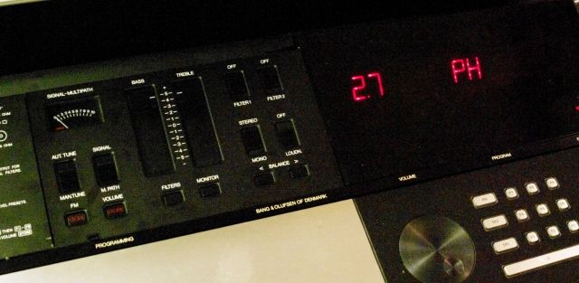
- The LED displays can be repaired by changing the SMD mounted LEDs with our SMD LED. Plaese note that all LEDs should be replaced in one display at the same time due to differences in luminance.
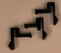
- If the right hand side aluminium plate damping dont work then check if the plastic link is broken. It can be replaced by our on demand made link.
7